
Operation Main Point for Indirect Heater
Senoil Fire-tube indirect heater is a skidded package designed and manufactured for fluid heating, cooperated with temperature and pressure measuring. Before startup, the inlet and outlet line have to be linked into the gas gathering and transferring process.
- Technical Parameter
Atmospheric pressure: 0.1013 MPa
Required minimum inlet temperature: 20℃.
Outlet temperature: ≥30℃
Inlet pressure: 5.65 ~ 12.0 MPa.
Outlet pressure: 4.60 ~ 6.40 MPa
Coil design pressure: 35 MPa.
Coil design temperature: 120℃.
- Structure
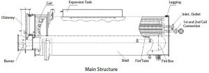
Indirect heater consist of heating coils, expansion tank, fire box, fire tube, shell, burner, chimney, flanged cover, saddle support, insulation and other parts.
Flanged covers are used on the shell at both ends. The shell is fitted with a level gauge. The filling water port and chemical port are used for adjust the water level and water quality. On the top of the shell is fitted with a temperature sensor and a thermometer to monitor the temperature of the water bath. On the bottom of the shell there is a drain hole to drain the polluted water. Both the coils and fire tube is designed removable from the shell, and capable to freely thermal expand in the shell. Plus, a sampling port and a thermometer port are reserved on chimney for flue gas analysis and temperature monitor if needed.
- Process Introduction
- Main Process Introduction
In most cases the effluent needs heating. The gate valve on by-pass line shall be cut off before startup. The effluent flows through union → hi-lo pilot → gate valve, keep open→ thermometer, display inlet effluent temperature → pressure transmitter, send pressure signal to PLC → temperature transmitter, send temperature signal to PLC → pressure gauge, display inlet effluent temperature → 1st coil →thermometer, display temperature after stage 1 heating → adjustable choke → thermometer, display temperature after throttling → 2nd coil → pressure gauge, display pressure after throttling → temperature transmitter, send temperature signal to PLC → pressure transmitter, send pressure signal to PLC → thermometer, display temperature after stage 2 heating → gate valve, keep open → hi-lo pilot → union, entering the next device unit.
- Fuel gas process Introduction
In most cases the fuel gas needs preheating. Close ball valve on the by-pass line. The outer fuel gas flows through union → ball valve, keep open → Y strainer , filter out impurities in fuel gas → scrubber, remove liquid from gas..
The clean and dehydrated fuel gas flows through ball valve, keep open → fuel gas preheating coil → ball valve, keep open → thermometer, display temperature after preheating → solenoid valve, power-on and keep it open → pressure transmitter, send temperature signal to PLC → safety cut-off valve, which cuts off the gas flow in case that pressure downstream 627 regulator exceeds set point → 627 regulator, stage 1 depressurizing → pressure gauge, display gas pressure after stage 1 depressurizing → 299H regulator, stage 2 depressurizing → pressure gauge, display gas pressure after stage 2 depressurizing.
- Chemical adding and water filling process description
When the heater is in service, the bath water may need refill and chemical adding. Close the ball valve on water filling line and open ball valve below the chemical adding port, and then add chemical into the bath water as needed. After that, close ball valve below the chemical adding port and open the ball valve on the water filling line, then fill water into the shell through quick coupler.
- Drainage Process Introduction
After a certain period of service or interior fouling, fill the heater with clean water and clean it up. And then open the ball valve on drainage line to drain off the sewage through the quick coupler. Then close the ball valve.
- Working Principle
First, the dosing ingredients (ethylene glycol) should enter into furnace body through dosing nozzle. And the soft water comes into the furnace by filling water nozzle to ensure moderate liquid water, whose level is shown on the liquid meter. The hot smoke and gas produced during the burning of fuel gas by burner in the fire tube flows into back part to the atmosphere through smoke tube and chimneys. The heat produced by the fuel gas into the fire tube will warm the water in the heating furnace, and then warm the equipment through the heating fuel gas in the coil.
Fuel gas is regulated on the pressure after the first and second class pressure regulating valve on the fuel pipe line, to satisfy the requirement of the burner and make the burner work stably. High pressure of the feed gas will come into the next device after primary heating coil, then through sulfur resistance throttle valve decompression and the secondary heating coil again.
- Operation
- General
- The operators of indirect heater shall be trained and certified before they operate the device
- The user is responsible for working out a standard operation procedure according to this manual and process Strictly comply with the SOP.
- Forbid the heater being operated in overpressure, over-temperature. Forbid frequent sudden-heating and sudden- cooling Forbid being operated in lower bath water level. It is strictly prohibited to operate without water.
- Operators shall strictly follow safety rules and Do regular or irregular inspection during operation and make records accordingly.
- Preparation
Pressure test shall pass before the device put into operation.
- The newly used device shall be with product qualification certificate and registered in the local quality
- After a long time shutdown, this device shall be inspected by qualified organization and pass before its
- Before operation make sure that all the parts and accessories are in good There shall be periodic calibration marks on PRV, pressure gauge, pressure transmitter, thermometer and temperature transmitter.
- Check water The normal water level is 840mm. If the water level is lower than lower limit,add some water. If the water level is higher than the upper limit, drain off the excessive water.
- Make sure that there is no leak in gas The corresponding valves and meters are in good condition.
- Check the fuel gas supply
- Make sure that inlet, outlet and middle connections are reliable and no Adjust valves and meters on input, output and middle pipelines to ensure the smooth flow of effluent.
- Chemical adding and water filling
After confirming that the fire is extinguished and the vent on expansion tank is open, clean the inside of the shell, and then fill up with water and add chemicals.
- Commissioning
- Open all relevant valves on fuel gas pipeline except solenoid Screw out pressure regulating bolts on regulator; loosen pressure regulating spring, therefore the pressure after regulator will be as low as possible. Then open solenoid valve and let gas flow in, tighten the pressure regulating bolts until the outlet pressure after first pressure regulation is 0.1MPa, and after second is 3~10KPa.
- For combustion system operation, please refer to burner operation
- Slowly warm up after igniting, do a 8-12 hour hot water
- During the test, the water level shall be controlled in a set range, and pressure of medium entered into coils shall be lower than work
- Adjust burner, temperature and other parameters in test, to achieve a stable operation
- Formal Operation Point
- If the commissioning test is passed, do formal operation according to the operation Note: Drain out condensation water from the outlet of furnace regularly.
- On-site inspection
- Check and keep record of the water level, inlet and outlet temperature, water bath temperature, flame condition and fuel gas pressure every 2 to 4 Adjust if some of them are not in normal range.
- Check the pressure gauge, pressure relief valve and level gauge Make sure they are calibrated.
- Check the valves and other If any damages are found, replace them immediately.
- If leakage is detected on shell, turn off the burner
- If leakage is detected on coils, turn off the burner Then open by-pass gate valve (50) and close gate valve and on input and out pipelines.
- If bath water somehow goes into fire box, turn off the burner
- Shutdown
- Normal shutdown
- Turn off the
- Cut off fuel gas
- Do not close the gate valve (30) and (40) on inlet and outlet pipeline untill the water bath temperature falls to 50℃.
- When for a short time the heater shuts down and well effluent is still fed through coils, it is acceptable to have bath water retained in Otherwise it shall be drained off.
- If the heater shuts down for a long time, the water in heater needs to be drained Fuel gas supply and well effluent shall be cut off. Remove and maintain accessories.
- Power off the system if necessary.
- Emergency shutdown
- Emergency shutdown when the following happen:
Please refer to Indirect Heater Control System Operation Manual
- Emergency shutdown procedures
When there is an emergency, audible and visual alarm is activated.
- Press the emergency stop button on PLC panel
- Check fault messages on HMI screen
- Shoot troubles according to the fault messages
- After troubles are solved, press system reset The fault information and alarm will be removed.
- Press the start button, and the burner will
- Precautions
- During operation, the ball valve (9) on scrubber (10) shall keep open. It is not allowed to lock the valve or remove its operating handle. Plus, the vent on expansion tank shall be open
- The water bath shall be at atmospheric
- The work pressure of coil shall be within the design pressure range
- Automatic control system
Please refer to Operation Manual of 1150 kW Indirect Heater Control System
- Maintenance
- Heater Maintenance
- The operator shall do patrol inspection on meters and valves to guarantee they are in good condition. If there is any problem, report
- Periodically analyze the bath Make sure that water hardness is under 0.6mg/L and PH is between 8.5 and 12 according to requirement of GB/T1576-2008 Water Quality for Industrial Boilers.
- Irregularly analyze the If there is heavy dirt, clean the interior of heater.
- Descale the interior of If it is cannot be descaled by mechanical method, use acid descaling method.
- Heater Maintenance
Plus, clean the ash in firebox.
- After one-year’s running, take an overall inspection of the heater and establish the inspection timeline based on the heater’s
- If necessary, monitor the erosion of coils, especially the thickness of
- Maintain the fuel gas system at least once a
- When maintaining the heater, remove the burner from heater and maintain it
- Timely repair the damaged
- Timely replace the damaged gaskets in burner connectors and ash door
- Burner Maintenance
- Keep the appearance of burner
- Clean the air duct and control circuits every
- Check if cables between burner and control system are tight If there is any problem, timely solve them.
- Check if the air blast pressure and flow rate are in good
Maintain valves, meters and other accessories according to their operation manuals
Leave A Comment