
Chemical Injection Pump Operation Manual
Chemical InjectionPump is used to inject chemicals to well line upstream of choke manifold. Below is our standard product operation manual.
1. Operation instructions
1.1. Operating requirements
1)Select a stable and dry place which is not exposed to shocks.
2)Environment temperature: min. -10℃,max. 50℃.
3)Environment humidity must not exceed 95% to avoid frosting.
4)When assembling, the front and the back of the equipment should be clearly identified.
5)Drive air source of the chemical injection pump
Compressed air
Compressed air pressure: 6-10bar
Compressed air flow: ≥5,000Ln/min
6)Working medium: Ethanol or ethylene glycol
1.2. Main technical parameters
a) Volume of external storage tank: about 250L in 304 stainless steel
b) Material of high pressure pipes, fittings and valve bodies: 316SS
c) Maximum working pressure of the system: 350bar
d) Injection capacity of the system: 0.19m3/hr (When compressed air pressure is 5bar and flow >1,700Ln/min)
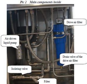
e) Air-driven liquid pump
Pressure ratio 1:117, maximum output pressure: 1000bar, output displacement: 36cm3/Double Stroke
1.3. Main functions and features
a) Manual opening/closure
Open control air source of the air-driven liquid pump manually
Adjust the air-driven pump control pressure manually
Shut off the high pressure loop manually
Release the high pressure loop manually
b) The system is designed with automatic stop and automatic pressurization functions. Open the drive air source shut-off valve of the air-driven liquid pump, and regulate control pressure slowly through the pressure regulator, the air-driven pump starts pressurizing automatically, and it would stop automatically when reaching needed pressure. When the system pressure decreases, the system starts automatically to pressurize.
c) Flow of the chemical injection pump per hour could be calculated roughly
through stroke counter(n.) of the air-driven pump. Q=36cm3 x n (Flow of each stroke is around 36 cm3)
d) The system is with overloading protection function.
e) The oil level is on real-time display.
f) The oil could be automatically filtered.
g) With indication functions for the air-driven pump control pressure, the system working pressure etc.
1.4. Pre-operation work
The customer should do as follows:
1) Open the whole packaging.
2) Read the user manual carefully.
3) The user is expected to be educated on safe operation and study the local safety regulations.
4) Check all the pipelines, especially high pressure sections, and make sure that they are not loose.
5) Installation of the chemical injection pump
Hoisting
Please make sure to use special hoisting apparatus for lifting and transferring of the chemical injection pump and storage tank for their heavy weight. Pay attention to safety during transfer and move slowly.
Make sure of sufficient space for installation, and sides and top of the equipment are well ventilated.
Make sure the spot is flat and dry, not exposed to shocks.
2) Installation of liquid inlet lines
The liquid inlet lines are stainless steel bellows. Connect one end to liquid inlet of the chemical injection pump, and the other end with feeding port of the storage tank.
2. Work before operation
Check if the equipment is installed reliably and stably.
Check for all pipeline and fitting connections. The fittings shall be firmly connected with no looseness.
Check for valve conditions
State of the liquid inlet ball valve
i. Open the ball valve at the storage tank outlet
ii. Close the drain valve of the storage tank
iii. Open the liquid inlet ball valve
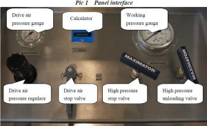
State of the drive air pressure regulator
Rotate the drive air pressure regulator of the air-driven liquid pump anti-clockwise to the loosest state.
State of the drive air shut-off valve
Turn the drive air shut-off valve to CLOSE state.
State of the high pressure shut-off valves and high pressure unloading valve
Open the high pressure shut-off valve, and rotate anti-clockwise to the loosest state; close the high pressure unloading valve, and rotate clockwise for tightening.
State of the drive air filter drain valve Close the drive air filter drain valve.
3. Operation method
3.1. Check before commissioning
Check of working medium. Add to top of the level meter.
Check for connection tightness of components
Check of set values
All the set values are well set before leaving factory. Check only the lock nuts of the bleed-off valve for looseness. Set values of the system are as below:
a) Factory setting of safety valve in the high pressure loop: 365±5bar
b) Factory setting of safety valve in the drive air loop: 6±0.5bar
3.2. Operation system
Pressurization
Open the drive air shut-off valve of the air-driven liquid pump, and slowly adjust the pressure regulator, then the air-driven pump starts working. The maximum working pressure is 350bar, and it’s adjustable as needed.
System unloading
Close the drive air shut-off valve of the air-driven liquid pump and open the high pressure unloading valve, then the system starting unloading.
4. Maintenance
4.1. Brief introduction
Maintenance work will guarantee longer and trouble-free utilization of the product. The following guidelines are based on our long-term experience.
1) All operations shall be carried out by trained or skilled personnel.
2)Before start of all maintenance work, make sure that the drive air of the equipment is cut off, to avoid the equipment from working during maintenance.
3) Before maintenance, please make sure all pressure in the equipment has been released.
4) Before starting of the equipment, please make sure all high pressure connections are checked for their tightness.
5)The operation staff must take safety precautions..
4.2. Maintenance work
4.2.1. Air driven liquid pump
It can work for over 2,000,000 times under normal circumstances. Please do not disassemble and repair by your own if failure occurs. Start the pump for a while regularly to avoid the aging of O-ring in case of long-time nonuse.
4.3. Maintenance
a) While the system is in operation, check visually the hydraulic line connections each week for leakage and in case of leakage, the connections shall be strengthened. Strengthening of the pipe joints, screws, adjusting screws, and the connecting pipelines once each week is recommended.
b) Check the storage tank liquid meter visually and make sure the liquid level maintain within the upper limit of the middle of the oil leveler. When it’s not sufficient, please supplement in time.
c) Repair or change timely for un-working units.
d) When abnormal conditions(for example: air driven pump starts at high frequency) occur at certain parts, timely analysis are needed instead of keeping on using to avoid wastage.
e) Annual check for once at least is recommended.
f) Spot check combined with regular check. Record and file
Leave A Comment