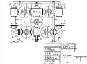
Choke manifold operation manual
Choke manifold is important equipment to be adopted in high pressure pipeline to reduce high pressure and protect downstream process equipment. So operation manual is also important. Below is some key points for operation and maintenance.
- Technical Specification
Nominal Bore Size: 3-1/16”
Working Pressure: 10,000 psi
Temperature Class: PU
Material Class: EE
Product Specification Level: PSL 3
Performance Requirement: PR1
- Installation Point
- Before installation, check all of the bolts, studs, nuts and If any cracks or thread damage to the parts, parts should be replaced. When connect flange, nuts should be tightened to the appropriate torque.
- It requires that there should be 2 ~ 3 threads out of nuts. After tightening torque, flange surface should be attached and parallel to each Gasket is low carbon steel with zinc plated or stainless steel material for H2S condition.
- Installing choke, there should use a new There is deformation of used gasket which can’t withstand working pressure. Whenever possible, install two gate valves in the upstream of the choke valve. At the downstream of choke is installed a gate. If need to remove, repair or inspect choke, gate valves should be closed.
- If need to install a “fire line”, it is better to be safe
- If valves are repaired, body hydrostatic test should be realized before working.
- Operation
- When stand by, the adjustable choke should be in full open
- Normal operation:
- It should be according to the stand pipe pressure, casing pressure, slurry pump stroke per minute(s) and the total
- Open or close the adjustable choke, to adjust the casing or stand pipe pressure (open the adjustable choke reduces pressure, closed throttle increases the pressure). Note: the possible congestion, casing or drill pipe pressure will be more than design pressure. In the event of the above situation, open the throttle fully to speed flowrate through adjustable choke. Once pressure drop to normal, please return to normal working When well condition is stable, and fixed choke is working, throttle should be open fully.
- If need to replace choke bean of fixed choke, open downstream gate valve of adjustable choke first. And then open upstream gate valve of adjustable choke. After that, close upstream and downstream gate valves of fixed choke.
- Maintenance
- When every job finished. Needle of adjustable choke and choke bean should be taken out to check. If there is any damage or corrosion, needle and choke bean should be replaced by new one. PS: choke bean gauge can be used to check orifice of choke bean.
- If there is too much sand, gates of gate valve should be open to check after period working.
- After choke repair or choke bean replaced, body hydrostatic should be test.
If there is any leakage, leakage reason should be inspected and leakage point to be fixed.
- Test Instruction
- Before hydrostatic test, valve should be fully open and adjustable choke should be fully open also.
- Block outlet of choke manifold and charge pressure into it. Charge pressure to 15,000psi. And hold 5 mins. If no leakage, relief pressure. Do the circle twice.
- Dismantling Instruction
- Removed valve from choke manifold
- Before repair of pressure control equipment, operator must pay attention and confirm there is no pressure in valves. If there is H2S, only H2S hazards trained personnel can operate adjustable choke.
- Confirm the adjustable choke in the full open position. Before dismantling, there should be no gas in adjustable choke. Unscrew flange nut one by one carefully until the gasket seal dropped. Do not remove the external connection flange nut until all the nut loose, separate the manifold flange and outlet flange, destroy the sealing ring, in order to avoid possible personal injury.
- Removed valve from choke manifold
- Storage Instruction
Test after drainage
Equipment shall be discharged before or after test and storage medium. Rust protection
Before storage, exposed metal parts and equipment shall be coated with 125.F the following not liquefied rust inhibitor
Assembly Drawing


Leave A Comment