
FC type gate valve operation manual
FC type gate valves are our common product supplied to many countries. So we hope our customer can find operation manual in our blog. And below is one manual for standard product.
1. Technical Specification
Gate valve, 3-1/16” x 10000psi, fc type, forged body, flanged end connection, EE, PU, PR1, PSL3.
2. Design Feature
2.1. The valve is a new kind of non-rising stem valve (without lift stem), whole height will not Change during operation, and has integrated gate which can be used in bi-direction.
2.2. Material of body is adopted according to oil condition, and is in accordance with requirements of 60K of API Spec.6A.
2.3. Body and bonnet connection are studded, and sealed with steel gasket, which eliminates corrosion to studs from cavity medium.
2.4. Gate and seat seal surface is thermal sprayed tungsten carbide, which has good performance of wear resistant and corrosion Resistant.
2.5. There is spring between body and seat, which provide seat with pre-tighten force, and make it possible to seal between gate and seat under low pressure.
2.6. Stem packing is high temperature resistant; perform high strength, wear and corrosion resisting.
3. Operation
3.1. Gates are shut-off parts moving along centerline of conduit vertically, used to cut off the conduit. Gates can only be on full open or full closed.
3.2. Handwheel must be turned back 1/4 to 1/2 circles when it is closed to the dead point.
3.3. Counter clockwise turning of the hand wheel is OPEN, clockwise turning is CLOSED.
3.4. Clean seal groove of flange before assembly, studded position should be free of missing or Less assembly. After studs be even tightened, and check distance between flanges.
3.5. It is recommended that body and seal test should be acted before using. If there is problem, trouble shooting is as below form.
| Trouble | Reasons | Action |
|
Pressure drops During body test |
Test blind plate leak
Fitting or needle valve leak Seal for bonnet flange leak
Stem seal leaks |
Check & Repair seal elements
Replace fitting and needle valve Evenly tighten the nuts or replace seal gasket
Replace packing or inject grease |
|
Pressure drops During seal test |
Test blind plate doesn’t seal or tighten studs
Grease in the body cavity is insufficient Gate and seat don’t float Seat or gate seal face are damaged O-ring of the gate is damaged |
Check & Repair seal elements
Fill grease Return handwheel 1/4 to 1/2 circles Replace seat or gate Replace O-ring |
| Back seal doesn’t work | Hasn’t screw out the bearing seat | Screw counter clock wise the bearing seat 2 to 3 circles |
4. Maintenance
4.1. Maintenance form
| Location | Maintenance | Repair |
| Bearing | Inject calcium–based grease to prevent Deterioration, pollution or insufficient | Replace those worn or damaged bearing couldn’t guarantee normal operation |
| Stem Packing | Often observe , no leakage permitted | Inject grease or replace stem seal ring |
| Bonnet. Seal gasket | Often observe , no leakage permitted | Tighten the nuts or replace seal gasket |
| Seat bore | Inject 7903 grease twice a year under normal | Check gate, seat and spring and perform replacement accordingly, replace O-ring every time when valve repaired |
4.2. Replace stem packing
4.2.1. Remove hand wheel, bearing seat, bearing, gland cover and stem packing
4.2.2. Clean and dry bonnet packing box, stem, gland cover, bearing seat and bearing, replace those parts which couldn’t be used and prepare good packing
4.2.3. Smear grease on the packing and put into the gland box, and assemble gland cover, bearing, bearing seat and handwheel. Be noted that bearing seat should be tighten to clock its bottom lock down screws.
4.2.4. Inject calcium-based grease into the bearing seat.
4.2.5. Carry out body test to inspect seal performance of the stem packing
4.3. Replace gate and seat
4.3.1. Release pressure in cavity, remove bonnet nuts, and take out bonnet assembly. Be noted to protect seal surface of gate & seat and stem & bonnet.
4.3.2. Take out gate and guide plate with thread tool
4.3.3. Clean gate, seat and valve cavity, check every seal surface and replace if there is any damage
4.3.4. Replace seat seal ring, assemble spring and seat
4.3.5. Put bonnet seal gasket into the flange groove
4.3.6. Coat 7903 grease on two seal faces of the gate, and connects with stem and assemble with body with bonnet. Gates shall be put into the cavity slowly, fit in the guide plate and between two seats. Be careful the grease fitting position cannot be unchanged.
4.3.7. Make studs on bonnet flange and be fixed in the thread hole.
4.3.8. Loosen special tool and take it out, hand wheel should be flexible, observe gate moving up and down well.
4.3.9. Inject 7903 grease from grease fitting on side of the bonnet to full.
4.3.10. Carry out body test and seal test on the valve
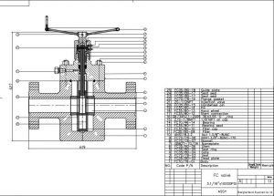
5. Assembly Drawing.
Leave A Comment